In this article we will see how to describe UART receiver in VHDL. First of all let's create a project in ISE:

I use XC6SLX9 FPGA chip from Xilinx. You need to chose your chip. Also you can use a different FPGA family, for example, Altera. In any case VHDL code should work for any chip. After the project has been created we need to add a VHDL source file. At the beginning of the file the used libraries need to be defined:
library IEEE;
use IEEE.STD_LOGIC_1164.ALL;
use IEEE.std_logic_unsigned.all;
use IEEE.NUMERIC_STD.ALL;
Then an interface should be defined:
entity My_UART is
port (
clk: in std_logic; -- ext. 25 MHz osc.
rx: in std_logic; -- UART receiver input
rx_byte: out std_logic_vector (7 downto 0) -- received byte
);
end My_UART;
The entity physical signals are commented above and do not need any explanation. After the entity follows the architecture:
architecture Behavioral of My_UART is
begin
end Behavioral;
Before a begin keyword all signals and constants are defined:
constant clk_freq: integer := 25_000_000; -- Osc. frequency
constant uart_baud: integer := 115200; -- UART baudrate
constant uart_freq: integer := clk_freq / (32 * uart_baud); -- UART system clock
signal uart_divider: integer range 0 to uart_freq; -- UART divider
signal uart_clk: std_logic; -- UART divider
signal cnt: integer range 0 to 15; -- UART clk counter
signal sample: std_logic; -- Flag of begining
UART receiver should support a 115200 kbps baudrate. But receiver should read a data on the input pin 16 times faster than actual UART transmit signal is changing. System clock 25 MHz is too high for this. That is why a simple divider is used:
-- sys_clk divider for generating uart_clk
process (clk)
begin
if (clk = '1' and clk'event) then
uart_divider <= uart_divider + 1;
if (uart_divider = uart_freq) then
uart_clk <= uart_clk xor '1';
uart_divider <= 0;
end if;
end if;
end process;
The main part of UART receiver is shown below. A finite state machine has been implemented in VHDL. When it receives a byte, it outputs it to the output.
process (uart_clk)
variable bitn: integer range 0 to 9 := 0; -- number of received bit
variable data: std_logic_vector (7 downto 0); -- received byte
variable rx_s: std_logic_vector (2 downto 0); -- bit sample variable
variable rx_b: std_logic; -- received bit true value
begin
if (uart_clk = '1' and uart_clk'event) then
if (rx_b = '1' and rx = '0') then -- start condition checking
sample <= '1';
rx_b := rx;
else
rx_b := rx;
end if;
if (cnt = 8) then -- 1st bit sample
rx_s(0) := rx;
end if;
if (cnt = 9) then -- 2nd bit sample
rx_s(1) := rx;
end if;
if (cnt = 10) then -- 3rd bit sample
rx_s(2) := rx;
end if;
if (cnt = 11) then -- if bit was sampled
-- Defining true bit value
rx_b := ((rx_s(0) and rx_s(1)) or (rx_s(1) and rx_s(2)) or ((rx_s(0) and rx_s(2))));
case (bitn) is
when 0 =>
if (rx = '0') then
bitn := 1;
else
bitn := 0;
sample <= '0';
end if;
when 1 => data(0) := rx_b;
bitn := 2;
when 2 => data(1) := rx_b;
bitn := 3;
when 3 => data(2) := rx_b;
bitn := 4;
when 4 => data(3) := rx_b;
bitn := 5;
when 5 => data(4) := rx_b;
bitn := 6;
when 6 => data(5) := rx_b;
bitn := 7;
when 7 => data(6) := rx_b;
bitn := 8;
when 8 => data(7) := rx_b;
bitn := 9;
when 9 => bitn := 0;
sample <= '0';
if (rx = '1') then
rx_byte <= data; -- output received byte into port
end if;
end case;
end if;
end if;
end process;
To demonstrate that the UART receiver works, it is need to generate a bitstream for the FPGA. To do this a constraints file *.ucf should be added to the ISE project:
# PlanAhead Generated physical constraints
NET "rx_byte[1]" LOC = P2;
NET "rx_byte[0]" LOC = P1;
NET "rx_byte[2]" LOC = P5;
NET "rx_byte[3]" LOC = P6;
NET "rx_byte[4]" LOC = P7;
NET "rx_byte[5]" LOC = P8;
NET "rx_byte[6]" LOC = P9;
NET "rx_byte[7]" LOC= P10;
NET "clk" LOC = P85;
NET "rx" LOC = P11;
# PlanAhead Generated IO constraints
NET "rx_byte[0]" IOSTANDARD = LVCMOS33;
NET "rx_byte[1]" IOSTANDARD = LVCMOS33;
NET "rx_byte[2]" IOSTANDARD = LVCMOS33;
NET "rx_byte[3]" IOSTANDARD = LVCMOS33;
NET "rx_byte[4]" IOSTANDARD = LVCMOS33;
NET "rx_byte[5]" IOSTANDARD = LVCMOS33;
NET "rx_byte[6]" IOSTANDARD = LVCMOS33;
NET "rx_byte[7]" IOSTANDARD = LVCMOS33;
NET "clk" IOSTANDARD = LVCMOS33;
NET "rx" IOSTANDARD = LVCMOS33;
After the bit stream generation you will get a following picture:

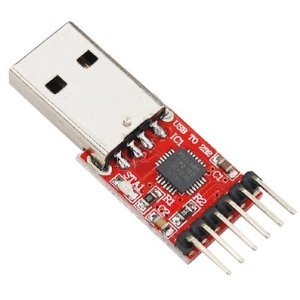
As a UART transmitter it is possible to use any USB-UART CP2102 converter like this:
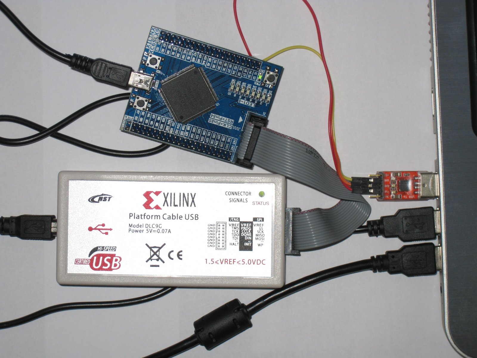
My setup looks like this:
The source code can be taken from here. :)