This project describes how to transmit digital audio using the STM32 microcontroller and NRF24L01 radio module. A task can be described in the following manner. The audio signal is being continuously transmitted from the transmitter to the receiver side. Each side (receiver and transmitter) must have STM32 MCU and NRF24L01 module. The input audio signal is converted from the analog to a digital form at the transmitter side using STM32 internal ADC. Although it is not the best solution, it has been decided to use a ready PCB with an MCU. The quality of the audio is satisfactory. This is because the ADC resolution is 12bit only. The analog and digital ground are connected on the target PCB and low sampling frequency (about 20 kHz). Also, PWM can distort the output audio signal. A more detailed overview of this project is shown below. To understand the system architecture, you can refer to a system block diagram in figure 1.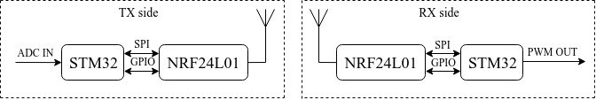
Figure 1. System block diagram
At each side, the same MCU and radio module are used. STM32F103CBT6 MCU has 128 kB of internal flash memory and 20 KB of RAM. Its core runs at 72 MHz frequency — a more detailed overview of this particular MCU you can find here. NRF24L01 is a single chip 2.4 GHz transceiver with an embedded baseband protocol engine (Enhanced Shock Burst), suitable for ultra-low-power wireless applications. More detailed information about the NRF24L01 chip you can find here.
The operation of the transmitter can be described as follows. An audio signal from the line output goes to the internal STM32 ADC analog input. ADC has a 12-bit resolution. Each 100 us the ADC takes a sample from the input and converts it into a 12-bit digital value. The STM32 internal DMA (direct memory access) manages data from the ADC to the RAM audio buffer. The audio buffer consists of two separate equal parts with 1280 int words (2560 bytes) in each of those. A buffer size has been defined empirically to eliminate too big an audio delay and efficiently use system resources. It can be simply redefined by changing a constant. Double bufferization is used to eliminate audio breaks. While one part of the audio buffer is transferred, the other part is filled in with data from the ADC by the DMA. The system is designed so that the audio buffer transmission process takes less time than filling in the data buffer. This is another prevention technique to eliminate audio pauses.
Once the buffer has been filled in with data, the MCU starts to send the buffer contents to the NRF24L01. The data is split into 32 bytes chunks and sent to the NRF24L01. The transmission of a 32-byte packet takes approximately 0,47 ms (if the packet is transmitted successfully). To check this judgment, a simple measurement has been carried out by using a logic analyzer. Whenever a packet is being transmitted, a dedicated MCU pin acquires a high logical level. A timing diagram for this is shown in figure 2.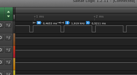
Figure 2.Timing diagram of packets transmission
Figure 3 shows that the average transmission time of the entire audio buffer takes about 41,6 ms.

Figure 3.Timing diagram of packets transmission
Figure 4 shows that the system's throughput can be increased because there are available time slots in the data transmission. The time between the two closest transmission intervals is about 86,4 ms.
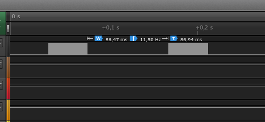
Figure 4.Timing diagram of packets transmission
The NRF24L01 has a built-in data transmission protocol that simplifies the handling of data packets. The SPI interface and 2 GPIOs control the chip operation at both transmitter and receiver sides. The system has enabled CRC error checking during data transmission. This feature usually is not necessary for such applications as audio streaming. However, it has not been removed, at least during the first iteration of the system design. The speed of air data transmission is 2 Mbps, but the 200 kbps data rate has been achieved only.
When a 32-byte data packet has been successfully transmitted, the NRF24L01 IRQ output pin sets to the low level (if SW has enabled such a feature). If a packet cannot be transmitted because a receiver cannot receive it, the transmitter sends the packet again. The firmware stops the ongoing transmission if the system cannot send the same data packet 15 times. The transmitter will not resend a packet more than 15 times because other data, which is being queued in the audio buffer, should be delivered in time to the receiver side. The built-in data transmission protocol allows the transmitter to receive and acknowledge packets from the receiver upon sending the data successfully.