- Details
- Written by Super User
- Category: Uncategorised
- Hits: 1321
Hello. Although making a plane was a relatively fast process, it is launch success history deserves individual attention. In 2020 I didn't know yet about the plane's center of gravity (CG) and why it is crucial. This article is not a tutorial about CG or how to make planes. It is just about my best memories of this plane.
The model itself is a seaplane according to its initial specification on the Internet. That was the reason why I decided to launch it for the first time at the Manniku lake in Estonia.
In this article we will see how to describe UART receiver in VHDL. First of all let's create a project in ISE:

I use XC6SLX9 FPGA chip from Xilinx. You need to chose your chip. Also you can use a different FPGA family, for example, Altera. In any case VHDL code should work for any chip. After the project has been created we need to add a VHDL source file. At the beginning of the file the used libraries need to be defined:
library IEEE;
use IEEE.STD_LOGIC_1164.ALL;
use IEEE.std_logic_unsigned.all;
use IEEE.NUMERIC_STD.ALL;
Then an interface should be defined:
entity My_UART is
port (
clk: in std_logic; -- ext. 25 MHz osc.
rx: in std_logic; -- UART receiver input
rx_byte: out std_logic_vector (7 downto 0) -- received byte
);
end My_UART;
The entity physical signals are commented above and do not need any explanation. After the entity follows the architecture:
architecture Behavioral of My_UART is
begin
end Behavioral;
Before a begin keyword all signals and constants are defined:
constant clk_freq: integer := 25_000_000; -- Osc. frequency
constant uart_baud: integer := 115200; -- UART baudrate
constant uart_freq: integer := clk_freq / (32 * uart_baud); -- UART system clock
signal uart_divider: integer range 0 to uart_freq; -- UART divider
signal uart_clk: std_logic; -- UART divider
signal cnt: integer range 0 to 15; -- UART clk counter
signal sample: std_logic; -- Flag of begining
UART receiver should support a 115200 kbps baudrate. But receiver should read a data on the input pin 16 times faster than actual UART transmit signal is changing. System clock 25 MHz is too high for this. That is why a simple divider is used:
-- sys_clk divider for generating uart_clk
process (clk)
begin
if (clk = '1' and clk'event) then
uart_divider <= uart_divider + 1;
if (uart_divider = uart_freq) then
uart_clk <= uart_clk xor '1';
uart_divider <= 0;
end if;
end if;
end process;
The main part of UART receiver is shown below. A finite state machine has been implemented in VHDL. When it receives a byte, it outputs it to the output.
process (uart_clk)
variable bitn: integer range 0 to 9 := 0; -- number of received bit
variable data: std_logic_vector (7 downto 0); -- received byte
variable rx_s: std_logic_vector (2 downto 0); -- bit sample variable
variable rx_b: std_logic; -- received bit true value
begin
if (uart_clk = '1' and uart_clk'event) then
if (rx_b = '1' and rx = '0') then -- start condition checking
sample <= '1';
rx_b := rx;
else
rx_b := rx;
end if;
if (cnt = 8) then -- 1st bit sample
rx_s(0) := rx;
end if;
if (cnt = 9) then -- 2nd bit sample
rx_s(1) := rx;
end if;
if (cnt = 10) then -- 3rd bit sample
rx_s(2) := rx;
end if;
if (cnt = 11) then -- if bit was sampled
-- Defining true bit value
rx_b := ((rx_s(0) and rx_s(1)) or (rx_s(1) and rx_s(2)) or ((rx_s(0) and rx_s(2))));
case (bitn) is
when 0 =>
if (rx = '0') then
bitn := 1;
else
bitn := 0;
sample <= '0';
end if;
when 1 => data(0) := rx_b;
bitn := 2;
when 2 => data(1) := rx_b;
bitn := 3;
when 3 => data(2) := rx_b;
bitn := 4;
when 4 => data(3) := rx_b;
bitn := 5;
when 5 => data(4) := rx_b;
bitn := 6;
when 6 => data(5) := rx_b;
bitn := 7;
when 7 => data(6) := rx_b;
bitn := 8;
when 8 => data(7) := rx_b;
bitn := 9;
when 9 => bitn := 0;
sample <= '0';
if (rx = '1') then
rx_byte <= data; -- output received byte into port
end if;
end case;
end if;
end if;
end process;
To demonstrate that the UART receiver works, it is need to generate a bitstream for the FPGA. To do this a constraints file *.ucf should be added to the ISE project:
# PlanAhead Generated physical constraints
NET "rx_byte[1]" LOC = P2;
NET "rx_byte[0]" LOC = P1;
NET "rx_byte[2]" LOC = P5;
NET "rx_byte[3]" LOC = P6;
NET "rx_byte[4]" LOC = P7;
NET "rx_byte[5]" LOC = P8;
NET "rx_byte[6]" LOC = P9;
NET "rx_byte[7]" LOC= P10;
NET "clk" LOC = P85;
NET "rx" LOC = P11;
# PlanAhead Generated IO constraints
NET "rx_byte[0]" IOSTANDARD = LVCMOS33;
NET "rx_byte[1]" IOSTANDARD = LVCMOS33;
NET "rx_byte[2]" IOSTANDARD = LVCMOS33;
NET "rx_byte[3]" IOSTANDARD = LVCMOS33;
NET "rx_byte[4]" IOSTANDARD = LVCMOS33;
NET "rx_byte[5]" IOSTANDARD = LVCMOS33;
NET "rx_byte[6]" IOSTANDARD = LVCMOS33;
NET "rx_byte[7]" IOSTANDARD = LVCMOS33;
NET "clk" IOSTANDARD = LVCMOS33;
NET "rx" IOSTANDARD = LVCMOS33;
After the bit stream generation you will get a following picture:

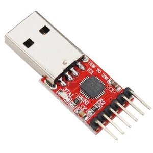
As a UART transmitter it is possible to use any USB-UART CP2102 converter like this:
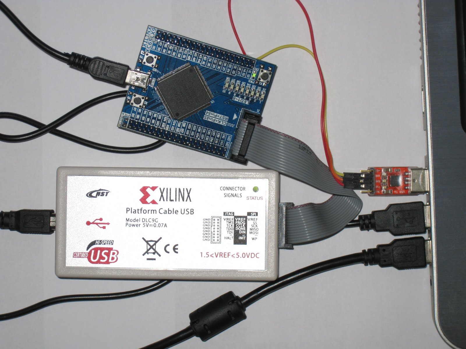
My setup looks like this:
The source code can be taken from here. :)
- Details
- Written by Super User
- Category: Uncategorised
- Hits: 2926
1) STM32F437xx audio-player. Flash - 2MB, RAM - 256kB, 4GB NAND Flash on board, FS-USB, leds, buttons, battery charger, debug micro HDMI connector, 3.5mm audio output, class D amplifier, connectors for Wi-Fi/Bluetooth module:


2) I2C controlled LED display:


3) Debug board for STM32F4Discovery kit:


4) STM32F103CBT6 + NRF24L01 debug board:


5) STM32 audio headset debug board:


